Circuit Diagrams and Ohm's law
Circuit Diagrams
- We already know that electric circuit is a continuous path consisting of cell (or a battery), a plug key, electrical component(s), and connecting wires.
- Electric circuits can be represented conveniently through a circuit diagram.
- A diagram which indicates how different components in a circuit have to be connected by using symbols for different electric components is called a circuit diagram.
- Table given below shows symbols used to represent some of the most commonly used electrical components

Ohm's Law
- Ohm's law is the relation between the potential difference applied to the ends of the conductor and current flowing through the conductor. This law was expressed by George Simon Ohm in 1826.
- Statement of Ohm's Law
If the physical state of the conductor (Temperature and mechanical strain etc.) remains unchanged, then current flowing through a conductor is always directly proportional to the potential difference across the two ends of the conductor
Mathematically
V ∝ I
or
V=IR
where constant of proportionality R is called the electric resistance or simply resistance of the conductor.
- Value of resistance depends upon the nature, dimension and physically dimensions of the conductor.
- From Ohm's Law
Thus electric resistance is the ratio of potential difference across the two ends of conductor and amount of current flowing through the conductor. - If a graph is drawn between the potential difference readings (V) and the corresponding current value (I), then the graph is found to be a straight line passing through the origin as shown below in the figure
- From graph we see that these two quantities V and I are directly proportional to one another.
- Also from this graph we see that current (I) increases with the potential difference (V) but their ratio V/I remain constant and this constant quantity as we have defined earlier is called the Resistance of the conductor.
- Electric resistance of a conductor is the obstruction offered by the conductor to the flow of the current through it.
- SI unit of resistance is Ohm (Ω) where 1 Ohm=1 volt/1 Ampere or 1Ω=1VA-1.
- The resistance of the conductor depends
- on its length,
- on its area of cross-section
- on the nature of its material
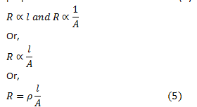
- Resistance of a uniform metallic conductor is directly proportional to its length (l) and inversely proportional to the area of cross-section (A). That is,
Where ρ is the constant of proportionality and is called the electrical resistivity of the material of the conductor. - The SI unit of resistivity is Ω m. It is a characteristic property of the material.
- The metals and alloys have very low resistivity in the range of 10-8 Ω m to 10-6 Ω m. They are good conductors of electricity.
- Insulators like rubber and glass have resistivity of the order of 1012 to 1017 Ω m.
- Both the resistance and resistivity of a material vary with temperature.


Comments
Post a Comment